|
|
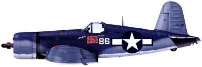
This Corsair will be built from 60 percent enlarged
Ziroli plans, with a wingspan of 152 inches, and a projected weight not
to exceed 75 pounds. I have Likes retracts, I will be making a home brewed
fiberglass cowling, and I have actually found a 1/3 scale canopy mold.
I also have a 1/3 scale full bodied pilot. Final scheme will be Pappy
Boyington's Corsair F4U-1A, Bureau Number 18086 "Lulubelle"
|
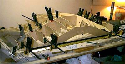 |
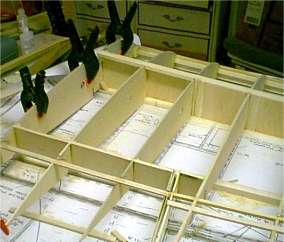
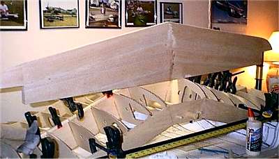
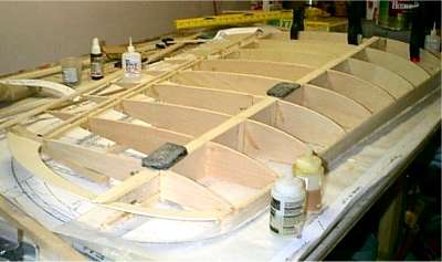
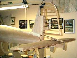
Center Section Construction
Details
|
The wing is framed with 3 main spars of 3/16 4 ply. These spars are all
one piece, cut from the full spar front view supplied on the plans. I
did not feel comfortable cutting spar valves and joining them with doublers.
All the ribs, except W3 and W4 are of 3/16 aircraft 4 ply, and all are
lightened, except for ribs 5 and 6 that the gear mount to, and rib 7,
which attached the outer panel. Ribs 3 and 4 are of 1/8 aircraft 5 ply.
Flaps will be mounted on the wing. The ribs fit very tightly on the spar,
and there was a concern toward getting a good glue joint. Any glue I used,
would be squirted out when I slid the ribs on the spar. So I decided to
install all of the ribs and wick them with thin CA. I then use triangle
stock to reinforce all of the joints. Where the ribs meet the front spar,
this is a butt joint. So to increase strength, I use 1/2 spruce triangle
stock utilizing Elmers Pro-Bond exterior wood glue. This glue is weather
(water) resistant, so should hold up to the cold, humidity and temperature
changes. Wood glue also provides a glue joint that is as strong, if not
stronger, than the wood.....very strong stuff. I did the same on the rear
spar where the ribs meet the aft spar. I also used triangle stock on the
center spar/rib joint. Since there is so much surface area here at the
center spar, I opted for 1/2 balsa triangle stock, and applied it with
the same wood glue in all 4 corners (both sides of the ribs and front
and back side). I am not as concerned with strength here, but rather a
good surface area glue joint to hold the rib in place.
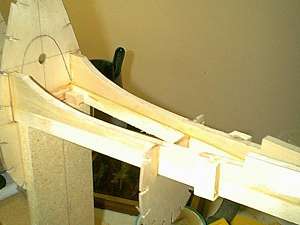
The design of the Corsair center section is, such that, everytime to
land, the stresses are wanting to break the wing at the top of the spar
"W" where the wing meets the fuse. With this in mind, I added
the doublers that would be otherwise used on the 2 piece spars and glued
them using T-88 Structural epoxy. I then added 1 inch Spruce triangle
stock at all of the W1/spar joints glued with T-88 Structural glue. T-88
is a very stable epoxy that is used in the building of homebuilt airplanes.
It does not soften up in the heat, nor does it become brittle in the cold.
ASTM test provide information that a lap joint using T-88 has a shear
strength of 2800 psi, resulting in substrate failure. Therefore, the wood
failed before the glue. This glue is available from Aircraft Spruce and
Specialty and is pretty inexpensive. All square stock spar insert pieces
are of 3/8 aspen pine. The center section, framed up, weighs 11 pounds
without the gear. Gear are from Likes with 13 inch struts using 9 inch
compressor tires.
|
Stab Construction Details
|
 |
The stab is built up with 3/16 balsa ribs, with 3/8 square
aspen pine spars. It was sheeted with 3/32 balsa. There were no major deviation
from the plans, but I did make some changes. Because the size of the stab
is 63 inches, which is equivalent to a 60 size plane's wing, I shear webbed
the spars with 1/16 balsa for rigidity. The trailing edge was also capped
with 1/16 ply to stiffen and increase strength. The stab will be glued (epoxied)
to the stab saddle. In addition, I will utilize a dowel pin in the front,
and will bolt it in, with the bolts encapsulated in epoxy, using 10-24 cap
head bolts. It will basically bolt on like a common RC wing attaches to
the fuse. Since the stab was so large, I figured the stresses involved left
it questionable as to whether or not simply gluing the stab to the saddle,
and relying on the balsa sheeting/stab glue joint, would hold up over time. |
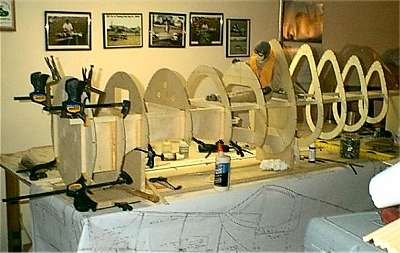
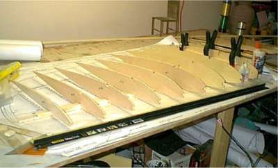
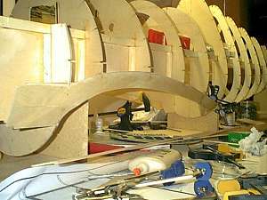
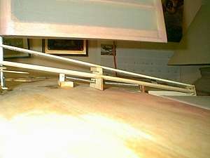
Wing Panel Construction
 |
|
|
The wing panels were framed using 3/8 x 3/4 Aspen pine from a 1x2 board
purchased at Menards and ripped on a band saw to fit. Aspen pine is a
great medium weight, straight grained wood that is very clean and really
soaks up the glue. It is also strong and rigid. The inboard rib is made
of 3/16 4 ply, and will be face glued to the outboard rib of the center
section. The next 2 ribs are of 1/8 5 play and was chosen to help support
and strengthen the wing joint brace attaching the outer panels to the
center section. The remainder of the ribs are of 3/16 balsa. The tip spine
piece is of 1/8 lite ply. All of the ribs were glued on using medium CA
from Balsa USA. I really like this glue, it seems to be the best out there
from what I have used.I shear webbed the front and back of the spars using
vertical grain 1/8 hard balsa with medium CA. This is a wing panel that
could be walked on. The only thing stronger than a boxed spar, would be
an I-beam spar...but that is a lot of work and not necessary.
The inner most rib bay was shear webbed with 1/8 5 ply glued in with
T-88 epoxy for its' strength, and was gusseted with 1 inch triangle stock
with this same T-88 epoxy. This area is where the wing joiner brace will
attach to the spars. I will then fill the are between the top and bottom
spar with a piece of hard wood. This will act as a continuation for the
main center section spar and should never fail. The inset sub leading
edge is of 3/8 square aspen pine with a 3/16 balsa leading edge sub cap.
After the wing is joined and sheeted, I will cap the leading edge with
1/2 inch balsa. There was no design deviation from the plans...only material
choice was changed.
|
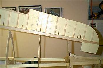
Wing panel nearing completion
After the wing is joined and sheeted, I will cap the leading
edge with 1/2 inch balsa. There was no design deviation from the plans...only
material choice was changed. Each wing panel measure 52 inches from inboard
rib to tip edge. |
 |
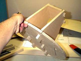
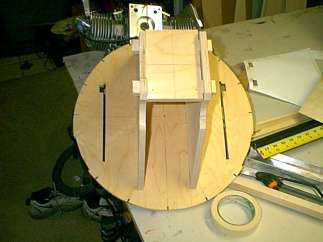
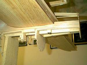
Motor Box and Firewall Construction
 |
|
|
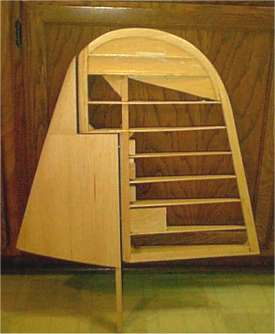
In this pic, you can see former F1 made of 1/2 inch 9 ply.
The slots to the side are to clear the 3/16 ply inner wing/fuse saddle.
You can see that the motor box sidewalls and the firewall itself is also
from 1/2 inch 9 ply. They are mortised into their adjacent structure and
will be pinned with 1/4 inch aluminum pins, and gusseted with spruce tri
stock as well. Once finished, this set-up will be bullet proof. T-88 structural
epoxy will be used throughout.
I have all of the formers cut out. I spent most of the night setting
up the firewall mount. I deviated from Ziolri's plans slightly. Former
#1 was cut from 1/2 inch 9 ply. I will be bringing the inner wing/fuse
saddle, made of 3/16 4 ply up through the firewall, but it will stop 1
inch forward of the firewall instead of continuing on to form the motor
box. I will gusset it front and back side with 1/2 inch spruce tri stock.
In case any of you hate cutting those 1/8 notches in the formers, a friend
of mine came up with a slick idea. We always trace the formers onto the
wood using carbon paper. Just mark the center of each notch and make a
tick mark 1/4 inch deep from the edge of the former (I use a compass set
to 1/4 inch and just run it around the perimeter of the former...works
pretty good). My buddy came up with the idea of putting a 1/8" wide
dado blade in his table
saw and just running the former in, back to the 1/4 inch tick mark. The
dado blade taper inward at the base of the cut, so you get a tight fit
with a squeeze at the base of the notch...almost don't need any glue.
I notched all the formers in about 15 minutes.
|
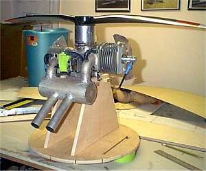 |
Husky 240CC
Here is a pic of the Husky 240CC sitting on the firewall with the 34x12
carbon fiber prop. |
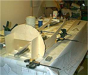
Fuse Construction
|
Started the crutch. Built up of 3/8x3/4 aspen pine with 3/16 hardwood
cross braces back to former #7, then 3/16 balsa reminder. The inner wing
saddles are from 3/16 4 ply and that is former #2 made of 3/16 4 ply as
well.
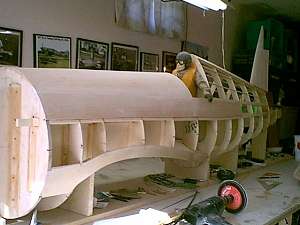
Second picture is the fuse up on the crutch jig. Formers F1 through
F11 are on. F1 is of 1/2 9 ply and will have the engine box attached.
F2 is of 3/16 ply with a 1/2 ply doubler around the big dowels. Formers
3 thru 7 are of 1/8 5 ply and will have the inner ((installed) and outer
wing saddle attached to them. F8-F11 are of 1/8 lite ply. F12-f14 are
1/8 5 ply and will have the tail retract installed on F12 (currently fitting).
The wing saddle will go between F12 and F13 (I will get a close up of
this are when installed). F-14 is the last former that ties everything
together and will have the balsa tail cone attached.
|
 |
Here is a snap shot of the outer wing saddle. This piece was cut from
1/8 5 ply and was quite a task to bend it down and around the body from
F6 to F7. Adding big gussets here to take off some of the load from the
formers. In this pic, you can also see that I have gussetted all of the
front end formers around the wing saddles to strengthen this area since
I plan on hoisting the plane within this area. Excuse the table mess...I
am running out of room.
|
Here is a shot of the stab saddle. To try and lighten this
area, yet make it strong, I laminated 1/4 balsa between 2 pieces of 1/6
ply. In this pic, you can also see that I did not cut out former 12. I left
it solid and drilled a 3/8 hole that the stab leading edge dowel will go
thru. Look closely, and you will see that I added a 3/8 x 3/4 piece of aspen
pine to the outside of the stab saddle and crutch. The stab was centered
and two 8-32 holes were drilled down between the outside of the wing saddle
and this aspen piece I added. There will be a T-Nut at the bottom to bolt
AND glue the stab to this saddle, just like a standard wing attachment.
Once there, always there |
 |
 |
A shot of the elevator being laid up. The core is of 1/8
lite ply, with a balsa leading edge and 3/16 balsa false ribs top and bottom.
Where the elevator is cut out on the back side there, I plan on installing
fake trim tabs, but operational balance (boost) tabs a-la full scale. I
have not decided yet, but I may add lightening holes every other rib bay
indicated by the pencil marks you see. I will be using some of Sierra Precisions
new 1/4 inch thick aluminum pin hinges. These things look tuff.
|
Been doing putzy work. Finished off the elevators and added
the lightening holes every other bay. Also made up the trim and boost tabs.
Built the vertical fin/rudder yesterday. Here is the assembly. i built them
per the plans, only I added a 1/16 ply backer to the rear side of the vertical
fin post for rigidity. Now, the only thing left to do is to fit the retracts,
figure out the servo installation and start sheeting |
 |
 |
Top of fuse front and top rear turtledeck have been sheeted.
The fin is installed. Fuse stringers are 1/8x1/4 aspen pine. Sheeting is
1/8 balsa. I should have the whole top half of the fuse sheeted by the end
of the weekend |
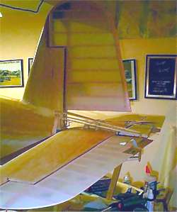
|
Well, I was able to get the tail feathers mounted and the fuse to all
sheeted down to the wing saddle. That is all the farther I can go on the
crutch jig. I will be removing it, adding all the radio gear and sealing
up the fuse bottom this week. Here is a 3/4 profile shot of the tail end.
The horizontal stab was mounted with a dowel through former F12 and two
8-32 bolts and T-nuts in the rear. The whole lot was epoxied down, never
to be removed again. IF you look at this photos, you will see the big
black blob on the rudder front, top air balance. This is the lead added
to balance the rudder. 4.5 oz.
|
 |
 |
Here is a close-up shot of the tail bottom. You can see the T-nuts that
hold the rear of the stab in. Also, just forward of the 1/2 former F13,
you can see the aspen blocks I have installed. I opted to put the servos
in the back, under the stab so that I could go with short, stiff control
rods and have everything out in the open for daily inspection. Small price
to pay since it is pretty well hidden under the stab. Hard to notice |
I have the tail feathers all on. Here is the spring I use
to help hold pressure off the servo (for taxiing, etc.). I also mass balanced
the elevators
|
 |
 |
Here is a picture of the rudder attached to the airframe.
It has been fabric covered, scale pinking tape applied and doped. The elevators
are also on and I have them fabric covered. I am in the process of applying
the pinking tape now. If you look at the elevator, you will see the mock
trim tab on the left elevator, and the functional boost tab on the right
elevator. Everything is reversed on one horizontal tailplane half. Vought
made one horizontal stab/elevator and used them interchangeably on either
side of the tail plane. As such, you will also find that access hatches
are located on the top of the left horizontal stab, and the bottom of the
right horizontal stab. A good idea for repairing battle damage. |
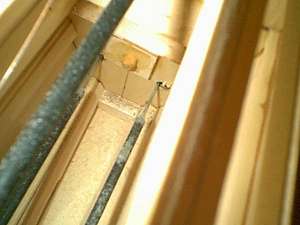
Fuse is now all sheeted, except for under the front end....until
after I fit the wing center section. Here is a shot showing the carbon fiber
arrow shaft rods for pull-pull on the rudder. Fitted with 4-40 ball link
fittings from Rocket City. The fiber rod on top is attached to an air cylinder
and the retractable tail wheel. The dowel rod you see poking through the
former is mounted into the stab, which is bolted to the stab saddle/crutch |
 |
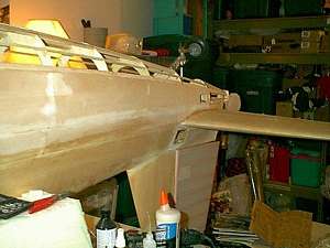 |
Here, the fuse has been removed from the crutch jig, and placed upside
down on some dense foam blocks to work on the internal linkages and fitting
of the retractable tail wheel. The top of the fuse has already been glassed,
and I have just finished adding the bottom stringers.
|
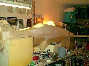
Here, the fuse has completed sheeting, except
for the very front, under the wing leading edge, which will wait until I
have fit the wing to the fuse. All up weight as you see the fuse is just
shy of 19 pounds.
|
 |
BACK to PROJECTS
|
|
Become an RCWarbrids site supporter by making a donation.
|
$5.00 |
 |
$10.00 |
|
$15.00 |
|
$20.00 |
|
| |
|
|
|
|